Alarms and Monitoring

In her day, Fir depended on the crew to report problems. As you would expect there are alarms throughout the boat. But, these systems only report locally. So, low oil pressure in a motor would only be reported to the engineers stationed in the engine room. The engineers would then report the problem to the Wheelhouse. Fir has scores of communication terminals scattered throughout the boat that allow a person with a handset to plugin and communicate with the Wheelhouse. The idea was that problems would be assessed locally then verbally forwarded to the Wheelhouse. It is a great system when you have a crew of 75.

Our plan requires a much smaller crew to be viable. Consequently, alarms and problems must be reported directly to the Wheelhouse.

Existing Alarms

Our first effort was to make certain that the existing alarms actually worked. We replaced all the lamps in the warning circuits. We had a hell of a time finding these bulbs in specialty bulb stores. Oddly enough, they are fairly common “appliance bulbs” at Lowes and Home Depot. We then went through the process of tripping each alarm to ensure that they reported correctly.

In addition to the above alarms, there were manual alarm switches for: general alarm, collision, and man overboard. These switches ran to an alarm box which does not appear to work. The manufacturer of the box wants $16,000 to replace the unit which is not in our budget. We suspect that the unit could easily be repaired by a board-level electrician. So…. working on that.

There are also mechanical switches in the galley that allow the fusible links in the galley hood and pull switches to annunciate a fire in the cooking equipment.

The question is: how do we move this information onto the N2K network that serves the entire boat. Maretron makes a black box (RIM100) that is designed to report when a circuit (AC or DC) is energized. It is usually used for motors and lights. We hooked these units to the existing alarm buzzers and warning lights so that an alarm off the existing system creates a network event on our N2K network. Maretron also makes a black box that monitors dry contacts.

We are still working with Maretron on the software side.

New Alarms

In addition to incorporating the existing systems into our N2K network, we have new devices. Again, we chose Maretron. We mounted a low Engine Room Bilge water level detector that will sound before the existing system. We have smoke/fire detectors in various locations within the engine room. We have added carbon monoxide detectors at key locations. We also added motion detectors that cover key passageways.

Monitoring

In this context, we refer to monitoring as the reporting of analogue data. Fir’s engine room has scores of gauges that measure pressure, temperature, and revolutions per minute. Again, none of this information was electronically reported to the Wheelhouse.

Based on reviews, we chose to use the Actisense EMU-1 to monitor each of the main engines (one unit for each motor). Out of the box, these units are designed to monitor a typical boat configuration i.e. RPMs, oil pressure, oil temperature, coolant temperature, etc. All of these types of information are “standard” messages on the N2K network meaning that a modern marine network knows how to treat oil pressure for engine #1. As soon has you associate the sensor with a use, the information pops up on the engine monitoring panel.

Of course, Fir is not typical for what the N2K designers had in mind. We have a lot more sensors than the typical recreational boat. Luckily, the standard allows for many “user defined” messages. One reason that we chose Maretron is that they offer a free software product called N2KAnalyzer. Once loaded on a PC, the software accesses the N2K network through a gateway that allows the PC to “see” all the devices on the network. Below is a screen shot of N2KAnalyzer as we begin the process. Each of the entries below have six channels which is to say they each report the results from six different sensors.

N2KAnalyzer Screen.jpg

All of this is information is deciphered and put on the N2K network which is carried by a single wire that winds its way around the boat. Anywhere the wire is present, we have the option to drop a display that allows access to all the information for the boat. So, we can drop displays in the captain’s quarters, crew quarters, galley, and owner’s state room with little trouble.

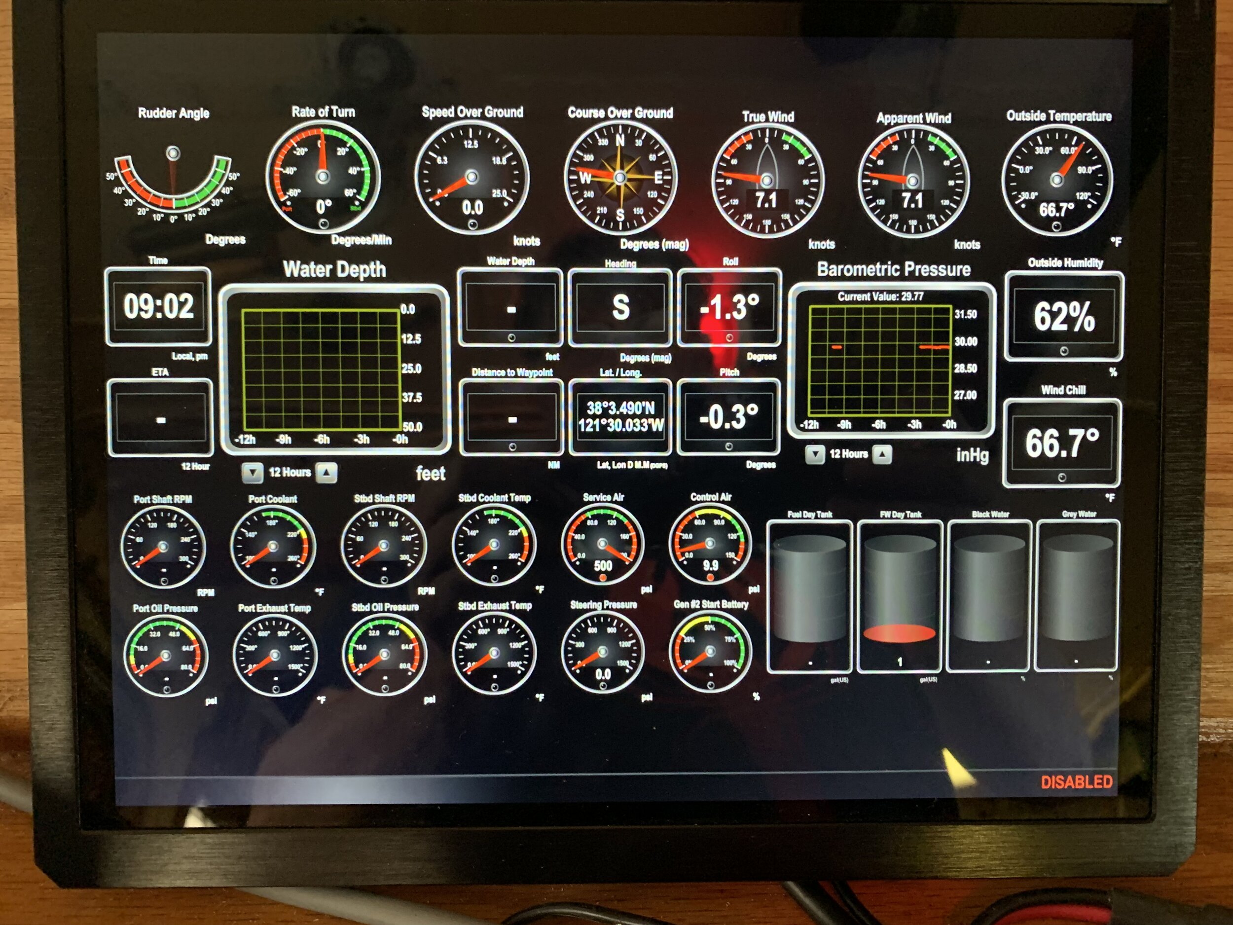
The other great aspect of Maretron is that we have near limitless control over the presentation of the information. All the big marine electronics companies allow you to build your own monitoring screens. But, they are geared toward modern systems. Fir’s main engines make 700-1200 revolutions per minute so a gauge that tops out at 4,000 RPM is really not that helpful. The same is true for oil pressure and fuel pressure which are much lower than most modern systems. Maretron allows you to create a custom scale and set your own yellow and red zones for each gauge. And, there are hundreds of other options.

We have started building about a dozen screens that incorporate and report this type of data. No doubt that there will be many future revisions. I suspect this is something that you always find yourself tweaking. Luckily, Maretron allows for this. Below is one screen in development. Obviously, this is a broad and complicated topic so expect to see future posts as we start to further develop the idea.

Monitoring Screens.jpg

Wheelhouse Electrical

As previously said, we have moved many of the controls and switches to the Wheelhouse. We are not completely changing out the systems. We are just getting the controls in a central location so we can reduce the crew count so as to make this effort a self-sustaining enterprise. In addition, we have added an emergency, LED lighting system that illuminates the engine room, galley and passage ways.

We have a deep bench In terms of redundancy. Our primary electrical source are two Kohler generators running in parallel that produce about 40KW each (80KW in total). We can squeak by with 40KW in most situations. Should both Kohlers go down, we have one of the original Detroit Diesels available at the turn of a switch which produces 100KW. We are working on a house battery bank that sits between the generators and the main AC distribution panels. Lastly, we have an uninteruptable power supply for the wheel house. The idea is that this last system will power the radios, emergency lighting, etc. the the event of the most dire emergency.

Batteries

There is a lot of information on the internet regarding lithium ion batteries vs. lead-acid batteries. So, we are not going into all the details. Fir does not care too much about battery weight and size because we have plenty of room and carrying capacity. But, lithium ion batteries charge more quickly, last longer, and can be discharged to a much lower level. If you baby your lead acid batteries then you can only draw them down to about half their rated capacity. A lithium ion battery can safely be drawn down to nearly zero so you get the amount of energy suggested by the sticker.

After some study, we decided to go with a unit from BigBattery.com. Their cost per KW is among the lowest available. They are serviceable meaning you can crack the case and replace a single cell if something goes wrong. They have an on/off switch and Anderson connectors (like the ones you see on electric golf cart chargers) which allows you to safely take the battery offline. The build quality appears above average based on several internet videos where users tear down battery units and examine the internal components.

We decided on two _____________. Each unit produces 288 amp hours at 24 volts for a total of 6 kilowatts. This is sufficient to run the wheelhouse electronics and emergency lighting for days. Each battery pack is about $2,000 delivered.

DC Distribution

We decided to go with a largely Victron system based on our own positive experience. Victron offers a modular distribution system. The Lynx Distributor is a fused DC busbar. We purchased two. One for the batteries to enter the bus bar. One for the DC current leaving the busbar. All the connections to the Lynx Distributors are fused so this is a fully protected system. Between the two Distributors is a Lynx shunt.

The shunt is basically a counting device. When the system is drawing down the batteries, the shunt measures the amount of energy going from the battery bank to the load. This coupled with battery voltage allows the Victron controller (Cerbo in our case) to determine that amount of power left in the battery. The reverse is also true. The shunt measures the amount of energy moving from the charger or alternative energy source to the battery.

The Victron Lynx system is modular so the 2 Lynx Distributors and Lynx shunt fit together with 8mm bolts such that the system looks like a single unit. This allows for a clean and organized installation.

Photovoltaic Sources

Fir has a lot of potential space for a solar farm. But, maximizing solar energy would

Charger/Inverter

Glass, Doors, and Windows

Glass

Apparently, plexiglass became a fad in the 1980s. The last major overhaul of the Fir occurred in 1988. At that time, the upper deck door windows were converted to plexiglass along with several portholes. Since that installation, time (32 years) and the sun have oxidized the plastic. Most became scored. Nearly all suffered from overspray when painting the hull.

We experimented with several glass options beginning with 5/16ths tempered glass. It only took a couple of Bay Area wind storms to slam the doors hard enough to leave shattered glass all over the deck. We then tried 1/4 inch laminated glass with an automotive U-channel type gasket. The U-channels looked great with a sharp, professional line separating the door and glass. Unfortunately, there is not enough room between the containment ring and door to accommodate the gasket. If the containment ring was not dead flat, torquing down the ring broke the glass. It was a tricky install.

Another complication was that the upper deck doors are hand drilled. Although they appear very similar, the spacing of the bolts in the containment ring varies from door to door by a small amount. We took our cue from the Coast Guard and installed the new glass using chalk. PPG Top Gun 400 is an elastomeric acrylic urethane that remains pliable as well as paintable. So far…. so good.

 
Glass%252BBefore.jpg
Glass After.jpg


Doors

Through most of her life, Fir had screen doors on every upper deck entrance. The doors pictured above opened outward and were secured to the house with brass fittings. Inside these doors were oak screen doors that opened inward and were secured by internal hardware. Previous ownership removed/sold/salvaged most of the screen doors, leaving only two attached to the old Wardroom. Hopefully, we can use these as patterns to replace many of the screen doors on the upper deck.

We want to dress up the Fir a bit without changing her character. With this in mind, we decided to “grain” the inside of the upper deck doors. “Graining” is a painting technique used to create the look of natural wood grain on a painted surface. You start with a very bright yellow base coating. This gets covered with a translucent brown, dragging the brush to create a woodgrain effect. Adding red and/or black, each coat following is more translucent producing the depth and characteristic seen in varnished wood.

Fir has three different types of wood throughout: oak, mahogany, and teak. Each one has reacted differently to time and exposure depending upon the location. For example, oak in the Wheelhouse has a very yellow tone, while the oak on the upper deck is much darker.

Pictured below is an incomplete door on the upper deck. It still has some problem areas and will need a clear coat when finished, but at first glance, it appears to be a pretty good match for the surrounding wood.

Windows

The window exteriors around the Wheelhouse have been a real pain in the ass. The forward windows leak and likely created one of the only areas of corrosion. This area happens to be in the crawlspace between the floor of the Wheelhouse and the ceiling of the Wardroom.

We decided to seal the side windows on the Wheelhouse where the glass is curved and seemingly the most obvious source of leaks. All these windows had copper frames. We cut new gaskets for the forward windows so that they can still be raised and lowered and have made it through the 2020 rainy season so…. so far, so good.

The exterior wooden frames of the Wheelhouse windows were not in great shape. While the frames had plenty of good wood available, there were gaps and essentially no protectant layer. After sanding, we applied Nautipoxy Penetrating Epoxy from Bonstone. We followed this with Bonstone Nautithane Pro. The results looked great, but 12 months later the top layer started to flake. We sanded again and applied a one-part solution from Interlux. Looked great, but it also started to flake. Now we are trying a clear coat of PPG’s PSX700. It looks great, today. Let's see how it lasts.

Aft Mast, Final Paint, Tender and Miscellaneous items in August 2018

Aft Mast


Work on the aft mast has lagged for several reasons.  First, it is a difficult climb. The A-frame in the front has a conventional ladder and there is a crows nest where you can stand.  I have a terrible fear of heights but I can muster the courage to climb the A-Frame.  The aft mast is similar to climbing a telephone pole, and there is no comfortable place to stand.  Furthermore, in order to work you have to trust a lanyard (in other words, let go with your hands and trust that the climbing harness will prevent you from falling to your certain death or quadriplegia). On our team, only Joe and Leo trust the lanyard.  Chris claims that he isn't afraid of falling, it’s landing that terrifies him.  My fear of heights makes me completely irrational at the sight of the aft mast.


Leo perched on the aft mast. His paint bucket hangs below. He is using an extension and 3 inch roller to paint the yardarms.

Leo perched on the aft mast. His paint bucket hangs below. He is using an extension and 3 inch roller to paint the yardarms.

The other time consuming part of dealing with the aft mast is that the surfaces have to be cleaned every time we turn to this project (i.e. between every coat of paint). The blueberry fields are about 100 yards from the Fir.  Birds feast on berries then sit on the guy wires at the top of both masts and crap all over the boat. So, every time we work on the mast, we begin by pressure washing. Getting the pressure washer set up to spray 56 feet above the waterline takes a couple of hours.

Getting the aft mast in shape is important for several reasons. At a bare minimum, masthead and anchor lights must be in place to USCG specifications (we are subject to the 50 meter rules which require two masthead lights and two anchor lights (more on this later). We also want to install several signal lights that we foresee will be required in situations consistent with our intended use.  In addition, we want to mount the correct USCG lighting sequence to indicate that our movements are "restricted."  We anticipate operating in areas where we are draft restricted (unable to significantly change course due to our draft).  In addition, there will be instances when no licensed pilot is onboard. The USCG light sequence to indicate these conditions is generally red, white, red (more on this later).  We have decided to utilize McDermott LED navigational lights.

The aft mast will be used for several antennas.  The most important is the antenna for our last resort VHF radio.  We have redundant VHF radios in the wheelhouse.  The VHF antenna off the aft mast will be a completely separate system.  We then have several media antennas. These antennas are important as a second source for weather information and internet access. However, these are primarily our entertainment antennas.

Early on, we decided on a few rules including: 1) let’s not do anything too stupid, and 2) let’s not waste money by doing things twice.  With these thoughts in mind, we decided to fully prepare and paint the aft mast before installing the lights and antennas.  We began by pressure washing the mast with our most aggressive turbo head.  We then used muriatic acid to treat the rust spots and followed with a treatment of PPG Duraprep 88 and washdown.  We touched-up rust spots, nooks, and crannies with PPG Amerlock Sealer followed by two coats of Amerlock 2/400 Light Tint Base.  We finished with two coats of PPG PSX700 Light Tint Base.  Due to birds love of the neighboring blueberry field as well as the Fir, a lot of time was spent cleaning between each coat. 


Antennas

One of our first decisions was to select Shakespeare as our "go to" antenna supplier.  Shakespeare manufactures all the antennas that we require (except the satellite TV antenna).  They have a fantastic line of commercial and military grade antennas. We wanted to work with one manufacturer in-order to have easily compatible set of connectors and mounts. In addition, a single source is much easier for troubleshooting. 

Shakespeare 5241-R Classic antenna.

Shakespeare 5241-R Classic antenna.

We chose the Shakespeare 5241 as our holly s--t backup VHF antenna.  We have redundant VHF radios in the wheelhouse that connect to separate Shakespeare antennas.  These are high gain, 9 dB antennas that ought to be the best fit for Fir and our needs.  In certain circumstances (e.g. heavy roll and extreme heeling) where lower gain antennas perform better, we chose a 3 dB antenna for our VHF radio of last resort.  It is mounted 56 feet above the water line which gives us excellent line of sight.


The Shakespeare XXX installed. Note the blueberry fields to the lower right of the photograph.

The Shakespeare XXX installed. Note the blueberry fields to the lower right of the photograph.

We chose the Shakespeare XXX to extend our cellular range.  From a price/speed perspective, cellular connectivity fits between WIFI and satellite alternatives. This system is essentially a cellular repeater.  It grabs the cellular signal from a prime location (56 feet above the water line in our situation), amplifies the signal, then rebroadcasts the signal inside our boat.  This should improve reception for all cellular devices. Of course, the most important use is our cellular modem that provides internet access for one of our navigation systems.   

The Shakespeare Seawatch antenna installed on the yardarm. Note the wooden yardarm below. How are we going to refinish that?

The Shakespeare Seawatch antenna installed on the yardarm. Note the wooden yardarm below. How are we going to refinish that?

We chose the Shakespeare XXX system for over the air television.  Over the air television is an antiquated idea in most of the US. But, it is still available in most US costal markets.  And, it is available in nearly every lesser developed market.

The Shakespeare XXX installed. The farm in the background is owned by Paris Hilton's grandfather.

The Shakespeare XXX installed. The farm in the background is owned by Paris Hilton's grandfather.

Spotlights

Fir was originally equipped with two 115 volts AC spotlights.  They were mounted to the top of the wheelhouse with two wooden bases. Over the years the wood bases were covered with some type of bute roofing material. Even with this treatment, the wood eventually rotted to the point where there was a leak in the wheelhouse and the mechanical system wobbled. We looked at a plastic replacement that would last forever. but Chis suggested that we use some teak from Aurora.  Aurora had 2X6 teak rails and decking, so we harvested a small portion of what Chris had to offer. After pulling nails and chipping off glue we managed to salvage eight pieces about 30 inches in length.  The pieces were joined together, cut into disks, and planned flat.  


Our spotlight bases after their first coat of Nautipoxy.

Our spotlight bases after their first coat of Nautipoxy.

Video Block
Double-click here to add a video by URL or embed code. Learn more
One spotlight base after the first coat of Nautithane.

One spotlight base after the first coat of Nautithane.

Cultural Diversion

Several members of our painting crew (Leo, Poochy, Harold, and Edward) are Native Americans. One reason that they may not be available for work is that they have Pow Wow.  Most days, I go to sleep shortly after the workers leave. I am beat from the 100 degree heat and there is no AC on Fir. Further, I am generally on East Coast time. But, this trip I decided to check out the Pow Wow.

Video Block
Double-click here to add a video by URL or embed code. Learn more
An "Indian Taco" served at Pow Wow. Basically, this is a grilled flatbread covered with seasoned meat, cheese, lettuce, and tomato.

An "Indian Taco" served at Pow Wow. Basically, this is a grilled flatbread covered with seasoned meat, cheese, lettuce, and tomato.

Paint

We are getting to the end of our external painting. This is not to suggest that everything is perfect. But, all the metal (except for the deck) is properly protected from the elements.  And, we have final quality paint on most of the boat.  There are many small spots that will need attention. One reason that we chose the PPG line of industrial paints is that the PSX700 can be patched without leaving an obvious spot -- additional coats "melt" into the previous coats.


First time for a PPG mixing error. Note the color red before and after the bracket for the life vest container. We only had one gallon of red on hand so this effectively stopped us from finishing the detailed painting this trip.

First time for a PPG mixing error. Note the color red before and after the bracket for the life vest container. We only had one gallon of red on hand so this effectively stopped us from finishing the detailed painting this trip.

Tender

Video Block
Double-click here to add a video by URL or embed code. Learn more

Ouch!

Our safety record for this project has been good.  Everyone has had the displeasure of bumping their heads on a steel beam (Fir is very unforgiving in this respect) and the dock has caused some falls (I went fully in the drink twice over the winter) but that has been about it.  One reason is that we have the right climbing gear for work on the masts.  The other reason is that the main generators are usually off when workers are on board. So, there is not much chance of electrical shock or injury from a crane, winch, or pump getting turned on inadvertently.  We power most of the tools with extension cords and small generators kept on the buoy deck.

This trip I was rushing to pull an extension cord from the buoy deck to the engine room to fire up the internal potable water pump. When I descended the auxillary engine room stairs, the extension cord must have dislodged an old toolbox sitting on a shelf over the stairs. The tool box fell on my head and nearly knocked me out. When I regained my senses, I had a bloody head wound and a sprained ankle.  Nothing serious. But, it reminded me that everything on a boat should be strapped in place even if you are sitting in a calm delta.


Commissioning the New Generator

Exhaust

A big difference between the existing generator and our updated system is the exhaust. The existing generator exhaust is called a dry stack system which is just an exhaust pipe that exits to the outside air. In the case of the Fir, this is a 5-inch pipe that runs about 30 feet horizontally and another 30 feet vertically. We will keep this system for the existing Detroit Diesel 671 that we are keeping as a backup.

For several reasons, the existing dry stack will not work for our upgraded, primary generator system. First, our proposed system is a scaled system that only produces 50KVA at anchor. At this rate, the exhaust from a single motor producing 65HP would most likely cool and condense in a 5-inch exhaust pipe 60 feet in length. The condensate could run down the pipe and into the engine. This would be especially problematic if we take on diesel fuel with higher sulfur content than is available in the United States because sulfur exhaust derivatives can be highly corrosive. Second, the stack on Fir is located over the prime event and recreation deck. We want to avoid the noise, smell, and potential condensation spitting in this area.

Our solution is a modern, wet exhaust system for the new generators. Seawater brought into the engine’s heat exchanger is sprayed into the tail of the exhaust pipe to cool exhaust gases and muffle sound. The combination of water and gas then enters a traditional waterlift muffler. The waterlift muffler produces a gurgling, burping sound often associated with boat engines at idle. In our case, the waterlift muffler pumps the exhaust to an exhaust separator. Water is expelled below the waterline. Gases are expelled above the waterline. We turned to Dan at Soundown to design and build the exhaust system.

 
The exhaust system as designed by Soundown.  Note the drawing shows our plan to have two Kohler generators stacked.

The exhaust system as designed by Soundown. Note the drawing shows our plan to have two Kohler generators stacked.


Controls

Fir’s original electrical system was controlled in the Engine Room. We will eventually produce a video showing all the controls for the original generator. In short, you start the Detroit Diesel 671 without an electrical load. Once warm, the Woodward controller is engaged and the RPMs rise to around 3,600. At this point, you fine-tune the controls to produce 450 volts at 60 hertz. Manually closing the circuit breaker makes the power available to the master bus. “Generator #1” (our backup system) will continue to work in this way.

The new Kohler generators are regulated by the Decisionmaker 3500 controller mounted to the generator. This setup supports a remote display and controller in the Wheelhouse. A motorized circuit breaker automatically brings the unit online once the engine is up to speed and electrical production has stabilized.

Our first step was to run the emergency stop buttons for the new generator. This is a very simple, two-wire system. The generator will only run if the circuit is closed so any break along the run will cause the generator to shut down. Chris wired in the original stop switch located just outside the galley. He then added a new leg to the circuit for an emergency shutdown switch in the Wheelhouse.

Joe and Chris wired the remote display and control panel. We initially set-up the display in the engine room with the control wires coiled up on the generator. There are not a lot of connections but getting it right did require a call to Kent at Boatswain’s Locker. For the generator to produce 450 volts (Fir’s native voltage) we needed a few minutes from Kent and an engineer. Kent was happy to help even on a Saturday morning.

The other wiring was installed temporarily. Eventually, the Kohler auto paralleling bank of generators will feed into the existing lines used by the previous “ Generator #2". For this initial test, the output of the single Kohler is wired as a direct replacement of the previous generator.


Sound Comparison of the Old and New Generators

In the future, we will go into more detail. For now, this video is of our initial testing. We open with Generator #1 (Detroit Diesel 671) in operation. We then take Generator #1 offline at the main panel and shut down the motor. We follow by starting the Kohler generator and connect it to the main bus.

There is an obvious difference in sound. Less obvious is the reduced vibrations from the new unit. Also, the Kohler generator responds almost instantly to changes in the electrical load. Again, we will get into this in detail in upcoming reports.


Implications of the New Generator

Getting the new generator online should start a flurry of progress. Previous owners jury-rigged many basic systems so that they could run on 115VAC electricity from small home generators. Since we now have 450 Volt 3 phase generators, the original configurations can be restored and run as intended. One example is the pump for the potable water pictured below.

 
The PVC pipe from the main potable water system is feeding a standard 115V well pump.  Now that we have 3 phase current, we can remove the well pump and restore the piping to the original system.

The PVC pipe from the main potable water system is feeding a standard 115V well pump. Now that we have 3 phase current, we can remove the well pump and restore the piping to the original system.


Over the next several blogs, we will show how we revise the operating systems to function as were designed. Stay tuned for updates.

Loading the Generator and Crane Motor

Covid spiked in San Joaquin County, California, has caused some problems. I decided to fly into Reno and drive across the border instead of risking some crazy California quarantine. In good weather, the drive is only an extra 30 minutes. What I did not count on is that the route includes crossing the Sierra Nevada mountains. The journey took me through Carson Pass (elevation 10,500 feet) with snow accumulations of several feet each year. The day I arrived, the snow began. After purchasing chains for my rental car, 60 miles through the mountains took 2.5 hours. Big mistake. Instead of arriving at the boat at 6 pm, I arrived at 10 pm in the middle of a rainstorm (this is the rainy season for northern California).


The schedule for this trip was tight. Our generator was ready for installation, and the crane motor was ready for pickup. Another crane motor tested bad and was ready to drop. Also, for some time we have planned to bring a lot of heavy junk to the landfill and clear off the buoy deck. It would be a busy two days.

Landing the Generator

Marcy picked up the generator in Hayward from our friends at A1 Transmission & Marine. Dave used his crane to pick the generator off the truck. Dave then lifted the lid to the engine room and lowered the generator onto the main deck of the engine room. Chris and Joe used come-alongs to get the generator into place on the lower level of the engine room. The new Genset landed without a scratch. The generator is now mounted but no connections have been made.


Installing the Crane Motor

On an earlier trip, two of the crane motors we tested were defective. We pulled the motor for the whip and brought it to Ace Electric Motor and Pump in Stockton. Their process began by putting the motor in an oven to melt all the paint and insulation so they could start from bare metal. They rewound the coils, machined the shafts, replaced all the bearings, and gave it a nice new paint job. One of the larger issues is that the brake system is no longer supported. So, Ace had new brake shoes manufactured and rewound the solenoid switch. The motor is now about as good as new.

Chris took his pickup to collect the remanufactured unit. I guessed that the motor weighed about 500 pounds and would no trouble for his 1/2 ton truck. My estimation was off by a bit. Chris' truck crawled due to excessive weight, bottoming out at various places along the way back to the boat.

The installation went about as expected. This motor was located on the top of the crane where gravity helped. The task was to drop the motor between the boom lines of Fir’s crane. Dave, a seasoned crane operator, pulled this off with minimal difficulty.


Dropping the Second Motor

Fir’s crane has four motors attached to the boom: the vang to each side, the whip, and the primary lift. Two motors are mounted above the boom, and two are mounted below the boom. The motors have a pinion gear that sits on top of gears within the gearbox which eventually connects to the spool. With an upper motor, you can simply lift the motor out of the gearbox. Replacement is just as simple and made easier because there are locating pins.

Lower motors are more difficult because the motor hangs below the gearbox. We have a lot of tools on-board to assist in lifting equipment from above. However, do not have jacks and such to lift equipment from below. Joe and Dave decided that the best way to remove the lower motor was to move the entire unit (motor, gearbox, and spool) down to the deck. We could then invert the unit and lift the motor from above using the same technique as we used for the upper motor. The 1” bolts holding the gearbox had probably not been touched for 30+ years. The more difficult bolts had to be cut.


Covid and the holidays limited this to a 2-day work session, but we got a lot accomplished.

Generator Choice

It has taken a long time to decide on the generators but we finally have. Fir was initially fitted with two 100KW Detroit Diesel 671 generators that rarely ran at the same time. They could be paralleled but more often one was used to run the crane and the other was used to run the house systems. We want to replace one of the 671s with a new unit that is more energy-efficient and far less noisy. Also, we want to take advantage of the more modern systems such that the generators can be monitored and controlled by the Wheelhouse.

When Fir was in service her electrical load was fairly consistent. Her duties were predictable. The complement of sailors aboard, the demands from the galley, day-part schedules, the sanitary system were all predictable. Our repurposing creates a much different situation. We may have a few staff on board at anchor. We may have a hundred on board for an event. The previously installed system would certainly cover our anticipated needs, yet the generators would be running at less than 30% capacity for long periods. This is not inefficient, it is bad for the motor. We need a scalable system that allows us to run each generator at its optimal capacity without wasting fuel. And, we want a largely automated system that does not require numerous engineers to oversee.

We determined that the most basic operations (wheelhouse controls, steering, and starting the main engines) require about 32KW. The greatest demand comes from the air compressors and inductive heaters required to start the mains. We added in the fire pumps/dewatering pumps as these demands have to be covered at all times. At rest, 32KW is more than enough to cover the lights, galley equipment, potable water pumps, hot water, and sanitary system. Further, with some minor scavenging of the house system loads in an emergency, one can start the mains, fight a fire and dewater the boat. We decided that a 40KW generator (operating at about 80% of demand) best meets our needs. We will install two of these units so we have an additional layer of protection.

After some study, we settled on Northern Lights and Kohler as the preferred vendors. Northern Lights makes a great system. The Luger motor is rock solid. The controls are mechanical so they are very predictable, reliable, and repairable at sea. Kohler makes their own motors which are great for systems under 50 KW (John Deer probably make the best motor above 50KW). Kohler uses a circuit board controller called the Decision Maker 3500. It is available on generators above 16KW. The drawback with a circuit board controller is that you could need an electrical engineering degree to fix it and a software degree to program it. So, going with Kohler requires one to have a spare controller and there is a learning curve.

Because we are looking to scale our system based on demand, we wanted a system that can automatically parallel several generators. Fir’s existing system can be operated in parallel but, each time the two generators are joined, a person must manually synchronize the phases. This does not work if the generators are being brought on and offline based on demand. Both Northern Lights and Kohler offer automated solutions. Northern Lights offers a third-party package that will parallel two generators of the same output. Kohler offers an auto paralleling system that is built into its Decision Maker 3500 controller. One critical difference is that the Kohler system can parallel generators of different sizes which may be something we require when we get further into air conditioning. The Kohler system can organize the generators to best match the current load.

Worth noting here is that we intend to work with Victron and/or Tesla to develop a battery management system. The goal of the battery system is to have the generators run at 75% capacity whenever they are called online. To the extent that actual demand is less than production at 75%, the excess will be used to charge the battery system. Further, the battery system ought to smooth out spikes in demand, spikes caused by various motors, and short-lived operations.

Based on all of the above, we decided to go with Kohler. The Decisionmaker 3500 has been out for many years and field-tested. The unit comes from a single vendor so there will be no arguments about who is to blame for a problem. Since it will join generators of different outputs, the Decisionmaker 3500 is more flexible and the customer support feels right. Kent Prentice is our guy at Boatswain’s Locker and Kurt is our guy at the distributor( A1 Transmission). They have been helpful and responsive concerning system topography (Wye vs. Delta configurations). We have a good feeling that the system we designed on paper is going to show up in person. So, Kohler is our choice.

 
Kohler 40EKOZD Specification Page 1.jpg
 
 
Kohler 40EKOZD Specification Page 2.jpg
 
 
Kohler 40EKOZD Specification Page 3.jpg