This month we returned to find the Fir covered in ash from the California wildfires. The fires never came within 10 miles of the boat, but ash and the smell of smoke are everywhere.
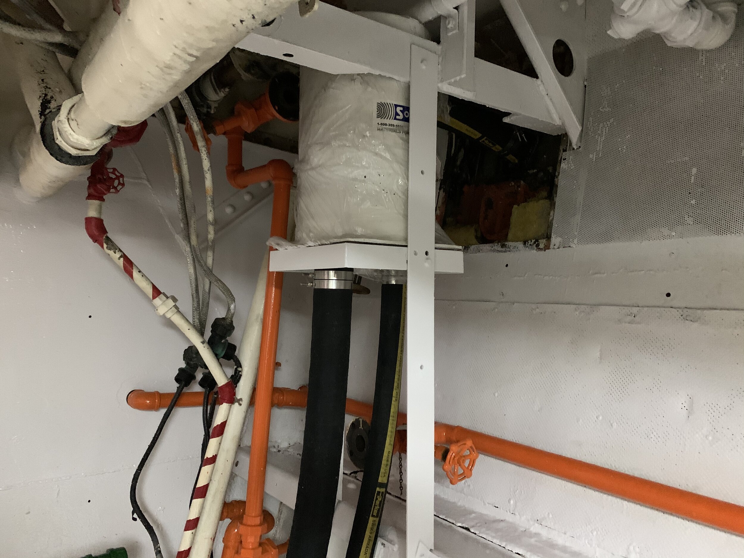
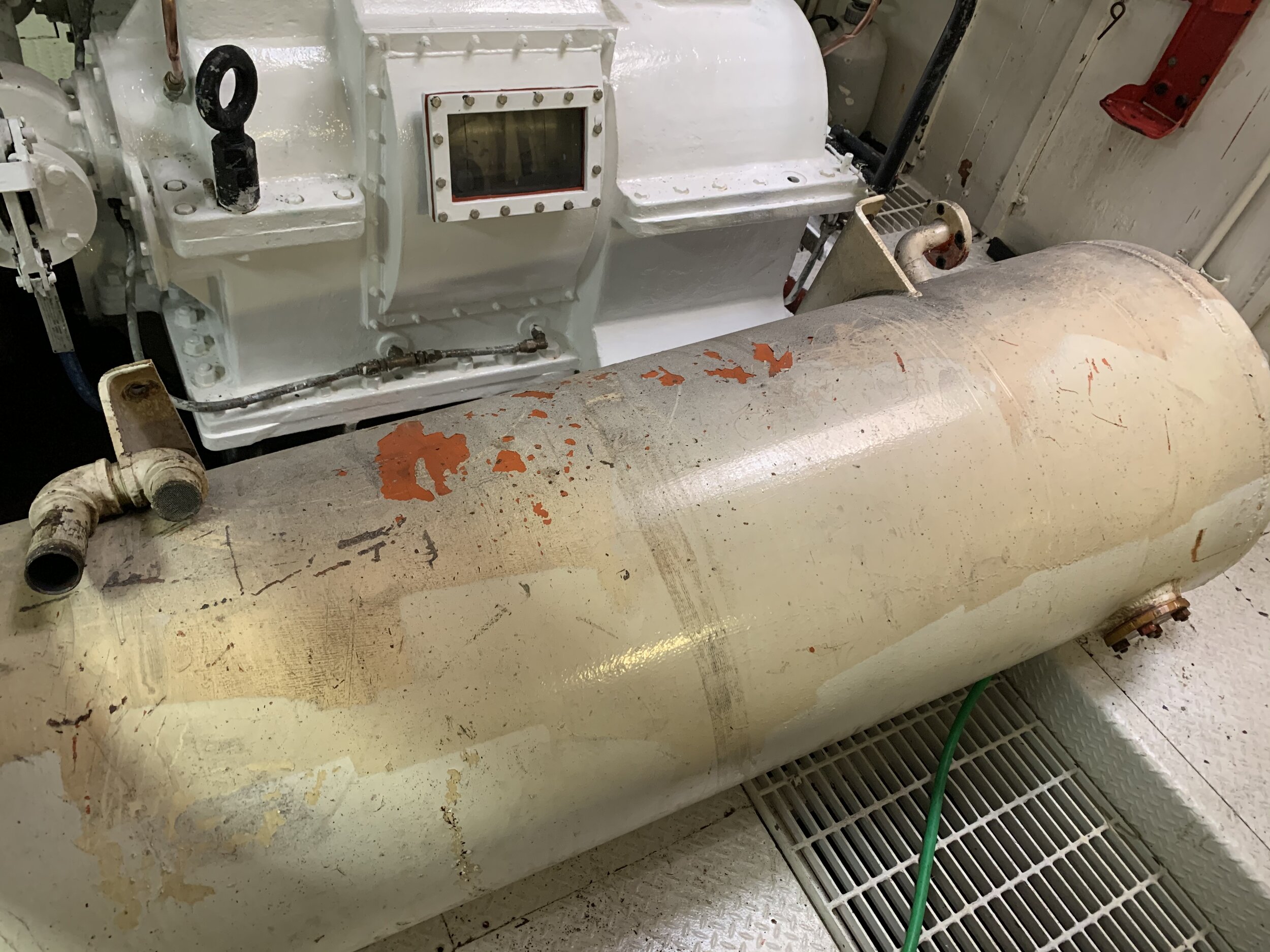
During each work session, we spend some amount of time evaluating, restoring, or replacing various engine room equipment. Getting parts is often an issue, so these projects tend to stretch out for several weeks. We have been lucky that the Coast Guard did a great job mothballing the boat and previous owners made few modifications. All the existing equipment appeared to work, yet some did not fit in our plans to return Fir to service. For example, the oily water separator was manufactured by a company that still exists, but they have not manufactured separators in more than 25 years. Replacement parts, manuals, and technical support are no longer available, rendering the equipment is unreliable. The diesel fired steam boiler, just by the way it looked, was too sketchy to test.
Our two generators work well, are still supported by the manufacturer, but are not up to date with current technology. We want to replace one of the generators with a modern system that is more fuel-efficient and far less noisy. Moreover, we want a contemporary system that can be controlled from the Wheelhouse.
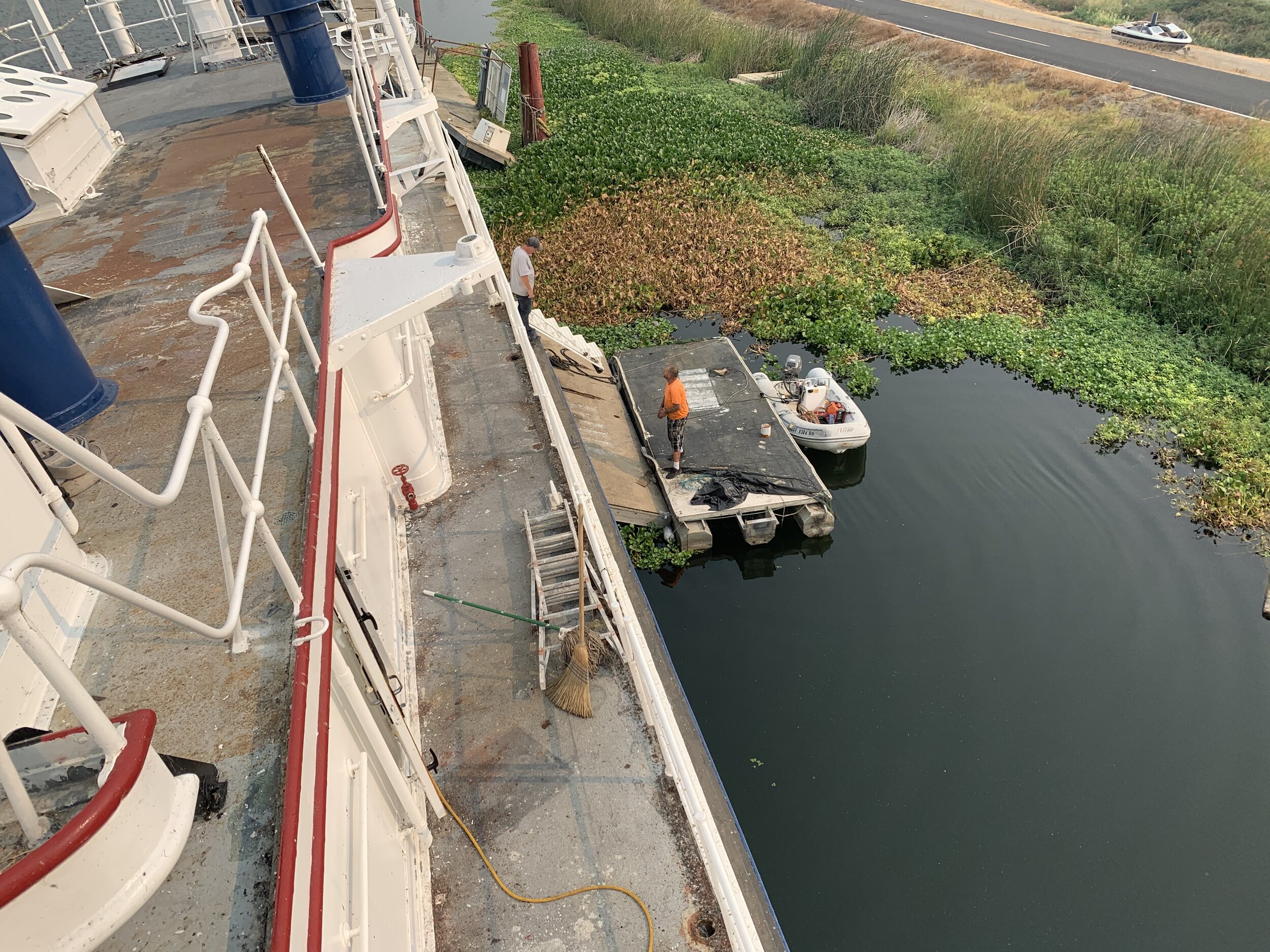
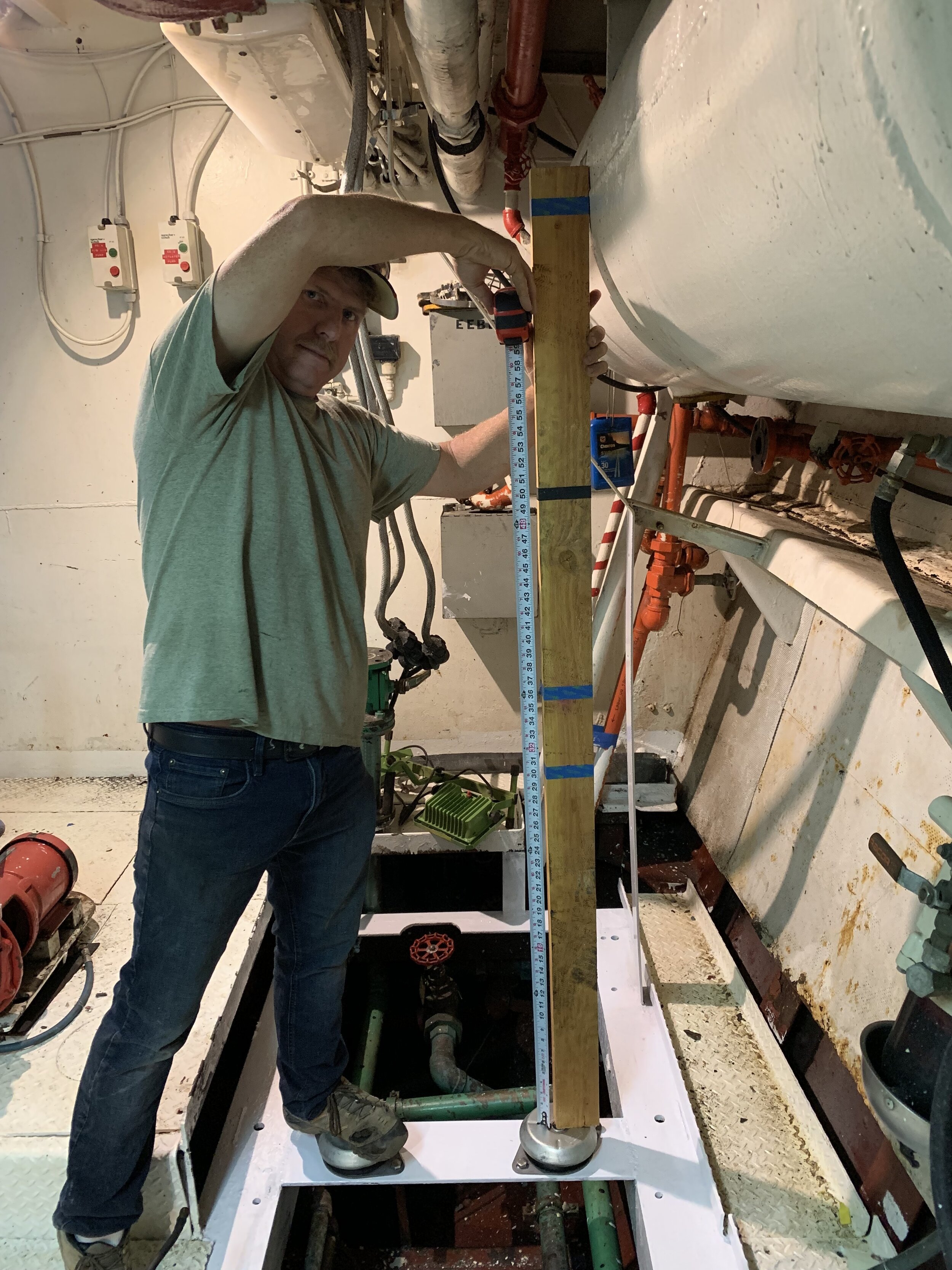
Re-working the engine room has resulted in a pile of old equipment that is either too large to pass through a 23-inch door and/or too heavy to move safely. This month, we brought in a crane to lift off the engine room hatch and move the old equipment to the buoy deck. We also took this opportunity to get one of the crane motors off the boat and into Joe’s truck so that it could be re-wound. When finished we loaded our tender back on the boat.

The original diesel fired boiler. We decided not to test the unit for fear of fire or CO poisoning.
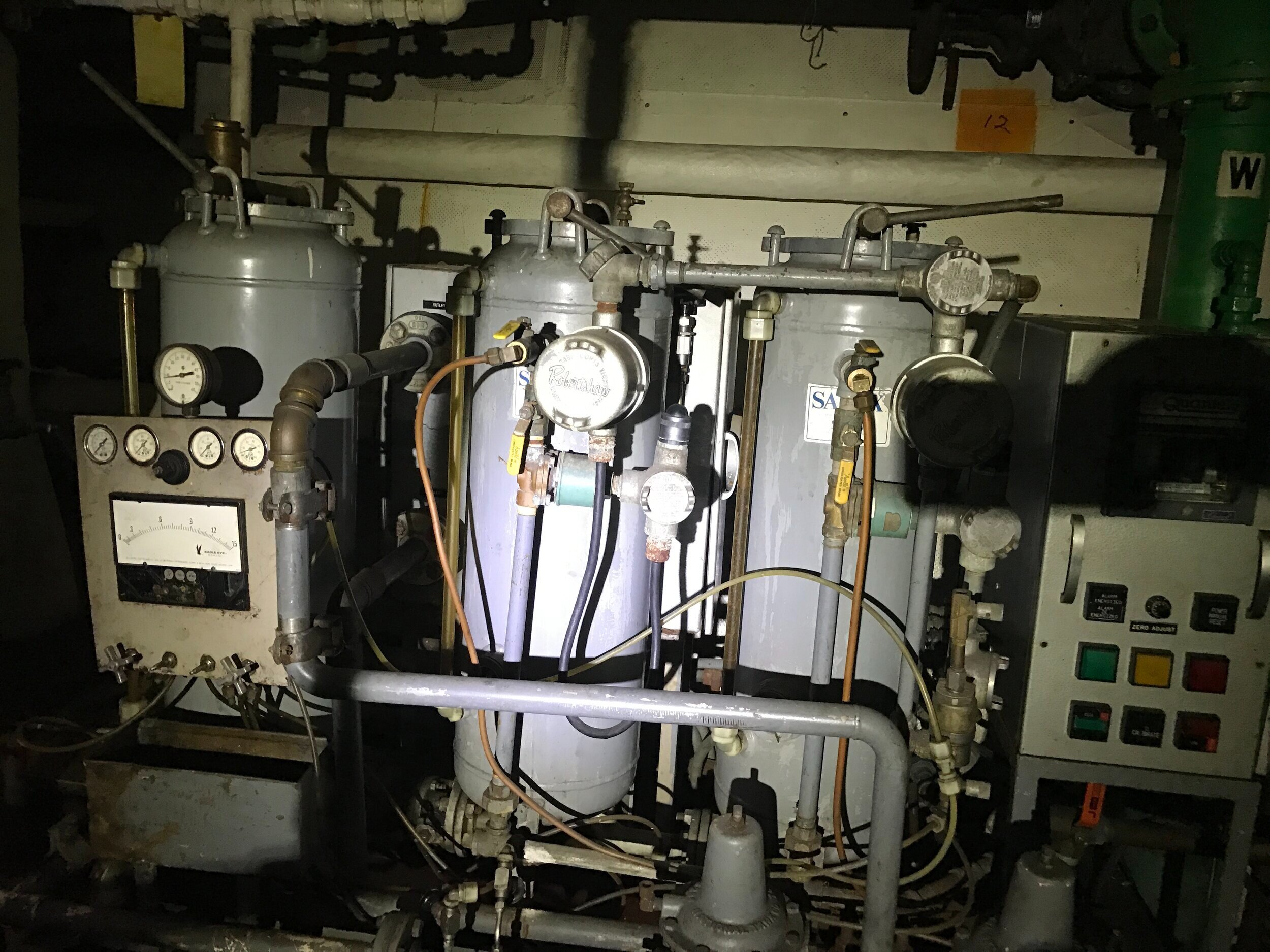
The original oily water separator. No longer supported by the manufacturer.
Next month we hope to finalize our plans with the generator and install a modern generator in place of the DD 671 that we removed this trip.